
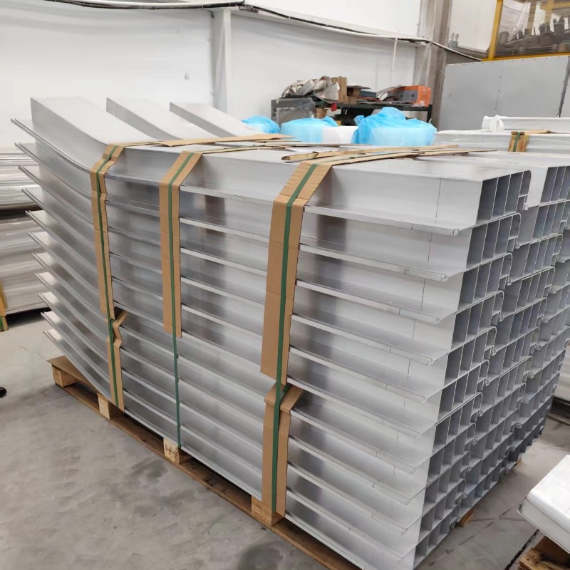
Aluminum Profile Bending
Mehrsegmentiges kontinuierliches Streckbiegen – 2 bis 5 Krümmungen
Kontinuierliches Streckbiegen von 2-5 Krümmungssektionen in einem Durchgang: glatte Übergänge ohne Falten, ≤±2 mm kumuliert, vom Datenpunktende geformt.
Produktdetails
There is a clear line between two things that are often described the same way. A multi-bend part made on a press brake has bends — discrete angles with straight sections between them. A multi-segment stretch-bent part has curvatures — a continuous form in which every point lies on some arc, and the arc changes from segment to segment.
We form 2–5 curvature segments continuously in one pass, in 6063-T5 and 6061-T6, with walls from 1 to 6 mm, a segment curvature error of ±0.4 mm, a cumulative curvature deviation of ≤±2 mm, and smooth transitions between segments, in lengths up to 6,500 mm.
Curvature, not angle
The distinction matters because it decides which failure you have to control.
| Multi-bend, press brake | Multi-segment, stretch bent | |
|---|---|---|
| Geometrie | Discrete angles, straight between | Continuous curvature, no straight unless specified |
| Control variable | Angle at each bend | Radius and arc length of each segment |
| Failure at a transition | A kink at the bend line | A crease where curvature changes abruptly |
| Werkzeuge | Die and punch per angle | Forming die per segment, plus tension control |
| Support through forming | Released and re-clamped between bends | Held under tension throughout |
The fifth row is the structural reason stretch bending is used for this class of part. In a press brake the part is released between bends, so each bend is formed from a stress state that starts at zero. In stretch bending the part stays under tension through all the segments, so the material state is continuous — which is what makes a smooth transition physically possible rather than something achieved by careful setting.
The transition: where a crease comes from
Where two segments of different curvature meet, the curvature has to change from one value to another. If it changes discontinuously, the surface shows a crease — a visible line where the material has been bent sharply enough to leave a mark.
Two ways to avoid it:
Programmed transition. The machine ramps the curvature from one value to the other over a short transition length. The result is geometrically continuous and there is no crease. This is a feature of the control system and of how the path was programmed, not of the die.
Deliberate transition segment. A short intermediate arc is formed between the two segments. It is a simpler approach and it needs the transition to be part of the drawing — otherwise the two segments meet directly and crease.
The failure is visible immediately on a reflective surface and only on a close look on a matt one, which is why it is worth agreeing the transition length rather than leaving it to the operator. On a decorative part, put the transition where it will not be seen; on a running surface, put it where the carriage travels straight.
Cumulative deviation: the ±2 mm budget
Each segment has its own curvature error. Over five segments those errors combine, and the cumulative figure of ≤±2 mm is the budget for all of them together.
That is a much tighter per-segment number than it appears. Two millimetres over five segments is roughly 0.4 mm per segment at the ends, and the errors do not average out — they add in the worst case. So the process has to be planned from the far end backwards: the last segment's curvature is set by where the part has to finish, not by its own nominal radius.
Two practical consequences:
- Form from the datum end. Fix the datum end, form toward it, and let the final segment absorb the accumulated error. If you form from both ends toward the middle, the error collects in the middle where it is hardest to correct.
- Check the cumulative figure, not only the segments. A part can have every segment within ±0.4 mm and be 3 mm out at the end. The check that catches this is an end-to-end measurement, not a set of local radius checks.
Spezifikationen
| Element | Referenzwert |
|---|---|
| Segments per part | 2–5 curvature segments, continuously formed |
| Wandstärke | 1–6 mm |
| Segment curvature error | ±0.4 mm |
| Cumulative curvature deviation | ≤±2 mm |
| Transition between segments | Smooth, no crease; transition length agreed |
| Maximale Länge | 6,500 mm |
| Legierungen | 6063-T5, 6061-T6 |
| Ausrüstung | CNC stretch bending machines, roll benders |
| Nachgelagert | CNC-Fräsen, Bohren, Gewindeschneiden, Schneiden |
| Oberflächenbehandlung | Eloxieren, Pulverbeschichtung |
| Standard | GB/T 6892-2023, ISO 9001 |
The segment forms, and what each one is for
| Form | Geometrie | Typische Verwendung | Watch out for |
|---|---|---|---|
| 2 segments, same direction | U-shaped curvature | Conveyor supports, base arc sections | Parallelism of the two ends |
| 2 segments, opposite direction | S-shaped curvature | Equipment connectors, transition rails | The inflection: no crease, no flat spot |
| 3 segments, compound | Multi-direction, multi-curvature | Compound frames, multi-curvature rails | Out-of-plane deviation; needs a checking fixture |
| 4–5 segments | Complex continuous form | Complex structural parts | Accumulated deviation; form from the datum end |
Note the "opposite direction" row specifically. An S-shape has a point of zero curvature at the inflection, and that is where a stretch-bent part is most likely to show a flat spot. The tension holds the section shape, but the curvature does pass through zero, and if the transition is short the flat is visible.
Why continuous forming holds accuracy better
Releasing and re-clamping a part introduces a new positioning error at every setup. On a multi-segment part formed in separate operations, those errors are independent of the curvature errors and they add to them.
Continuous forming removes that class of error entirely. The part is gripped once, the tension is applied once, and every segment is formed relative to the same datum. The remaining error is the machine's path accuracy plus the material's springback variation, and neither is amplified by re-clamping.
This is why the cumulative figure can be ≤±2 mm on a 6.5 m part. It is not that each segment is exceptionally accurate; it is that nothing is added between them.
Wo es nicht passt
- The design needs an angle, not a curve. A stretch-bent part has continuous curvature; a sharp corner is a different process. Use a press brake or a welded corner.
- The transition cannot be given length. Two arcs meeting at a point will crease. If the drawing does not allow a transition, the geometry has to change.
- The section is asymmetric and the segments reverse direction. The twist from the asymmetry changes sign at the inflection and the part corkscrews. Symmetrise the section.
- The part has to be welded after forming. Welding shrinkage changes the curvature, and on a five-segment part the change is not uniform. Pre-set the curvature if the welds are near the curve.
- The cumulative tolerance is tighter than ±2 mm on a long part. That is near the practical limit for five segments. Machine the end interfaces after forming instead.
- The quantity is a few pieces and every segment is different. Programming and a trial piece per segment is a real setup. For a handful of parts, consider a segmented fabrication with designed joints.
Was für ein Angebot zu senden ist
Send the section drawing, the curve definition segment by segment — radius, arc length and direction — the transition lengths if you have them, the alloy and temper, the quantity, and the datum end from which the part should be formed. If the curve is defined only by end points, tell us the deviation allowed from the true curve; otherwise several different curves satisfy the drawing.
We will reply with the forming plan, the transition treatment, the cumulative tolerance we can hold and how we would measure it, the checking fixture if the part is out of plane, and the per-segment and cumulative figures in writing. Where the transition cannot be formed without a crease, we will say so.
FAQ
What curvature accuracy can you hold across several segments?
Reference ±0.4 mm on each segment and ≤±2 mm cumulative over the part, with a smooth transition between segments. Those are capability references: the value on your order is set by your drawing, and on a multi-segment part the cumulative figure is the one that decides whether it assembles, so we confirm both in writing before you order.
What is the difference between this and single-segment stretch bending?
One curvature versus several, and therefore one springback compensation versus a varying one. It also introduces the transition between segments as a new failure mode: two different curvatures meeting without a transition will crease. And it introduces accumulated deviation, which is why the cumulative tolerance is specified separately.
How is the transition kept smooth?
By ramping the curvature over a transition length rather than switching it, either through the machine's programmed path or by forming a short intermediate arc. Both work; both need the transition to be defined. If the drawing shows two arcs meeting at a point with no transition, the part will crease at that point.
How is cumulative deviation controlled?
By forming from the datum end and letting the final segment absorb the accumulated error, and by measuring end to end rather than only at each segment. Checking the local radii will not detect a part where every segment is in tolerance and the end is 3 mm out.
Can the segments change direction?
Yes, including in different planes. An in-plane S is straightforward; an out-of-plane form needs a checking fixture, because the part can be correct in two projections and wrong in the third.
Kann es nach dem Umformen geschweißt werden?
Yes, with the caveat that welding shrinkage changes curvature. On a multi-segment part the change is not uniform along the length, so if welds fall near curved sections the curvature should be pre-set to allow for the closing. Tell us at enquiry.
Wie wird es kalkuliert?
On the number of curvature segments, the section, the length and the quantity. Each additional segment adds programming and forming time, and the trial piece is a setup cost on the first order. The checking fixture, if needed, is quoted separately.
Senden Sie Ihre Zeichnung
Email the section drawing, the segment-by-segment curve definition, the transition lengths and the datum end to linjunbing@truetrustlv.com, or send it on WhatsApp at +86 136 6644 0600. You will get a forming plan, a transition treatment and a written tolerance statement.
ANGEBOT ERHALTEN
Sobald Sie Ihre Anforderungen übermittelt haben, kontaktieren wir Sie so schnell wie möglich bezüglich Ihrer Produktanfrage.:Mehrsegmentiges kontinuierliches Streckbiegen – 2 bis 5 Krümmungen