
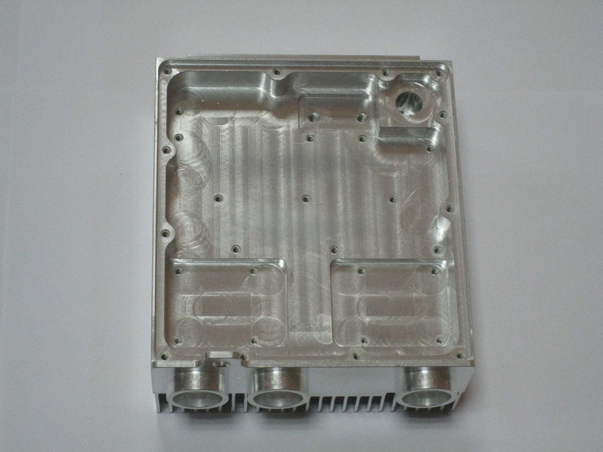
Custom Aluminum Profiles
CNC-Präzisionsbearbeitung von Aluminiumprofilen – Route und Reihenfolge
Dasselbe Teil, drei Wege, 40 % Preisunterschied. Wie man zwischen Sägen und Bohren, Bearbeiten und Matrize wählt und warum das Eloxieren im Toleranzbudget liegt.
Produktdetails
Two suppliers quote the same aluminium part at prices 40 per cent apart and both quotes are honest. The difference is rarely the hourly rate. It is the route: how many setups the part needs, whether the features are machined or extruded in, whether the part is machined before or after it is coated, and how much inspection the drawing implies.
This page is the overview of how a machined aluminium profile gets from a drawing to a finished part in our works — what the available routes are, what each one costs you in money and in tolerance, and the sequencing decisions that are easy to get wrong and expensive to correct afterwards. The individual processes have their own pages; this one is about choosing between them.
Reference capability across the works: ±0.01 to ±0.05 mm on machined features, Ra ≤ 1.6 µm standard, up to 6,500 × 550 × 500 mm, in 6061-T6, 6063-T5, 6005-T6, 6082-T6 and 7075-T5.
The same part, three routes, three prices
Take a 1,200 mm structural beam with a row of mounting holes, two machined pads at the ends that have to be coplanar, and an anodised finish. There are at least three ways to make it, and they are not equivalent:
- Cut, drill, anodise. Cheapest. The pads are sawn ends, the holes are drilled from the sawn end as a datum, and the coplanarity of the pads depends entirely on the squareness of the saw cut.
- Cut, mill the ends, drill from the milled face. Adds a setup. The pads are now machined and coplanar, the hole pattern is referenced to a real datum, and the part will assemble without preload.
- Extrude the pads into the section, cut and drill only. Highest tooling cost, lowest piece price. Viable only if the pad geometry is constant along the length and the volume justifies a die.
Each is correct for a different customer. The one that is wrong is the first, chosen by default because nobody asked what the pads were for.
Five routes, and what each one is for
| Route | Was es ist | Am besten für | Where the cost sits |
|---|---|---|---|
| A. Cut and drill | Saw to length, drill and tap, coat | Frames, guards, racks, general structure | Almost all material and saw time; very low setup |
| B. Cut, face, machine | Saw, mill the datum faces, then all features in one machining setup | Structural parts with position-critical holes or coplanar pads | Setup and programming; low per-piece at volume |
| C. Die then machine | New extrusion die carries the constant features; machining only for the variable ones | High volume with length-constant grooves, fins, rails | One-off die cost; very low piece price |
| D. Rough, relieve, finish | Machine, release stress, re-clamp, finish | Thin walls, tight flatness, large removed volumes | Extra handling and machine time |
| E. Turn-mill, one setup | Rotational and prismatic features from one grip | Sleeves, flanges, valve bodies, sensor housings | Higher setup, much lower per-piece time |
Routes B and D are often the same order. The distinction that matters commercially is whether the part is machined in one setup or three, because setup is what a small batch is actually paying for.
When the feature belongs in the die, not the machine
Extrusion is a forming process, and anything that is constant along the length of the profile comes out of the die for free once the die exists. A T-slot, a mounting rail, a fin array, a hinge knuckle, a wire channel, a screw boss that runs the full length: all of these cost money per part if they are milled and cost nothing per part if they are extruded.
The trade is a one-off die cost against a per-part saving, and the break-even is further away than most buyers expect. A new die is a design and tooling project — typically three to four weeks — and it only pays back when the section is complex enough that the machining it replaces is significant. As a rule of thumb:
- Simple section, one or two extra grooves: the die rarely pays back unless the annual volume is in the tens of thousands of pieces or the length is very long.
- Complex section replacing several milling operations: the die can pay back within a few thousand metres of profile, and then the piece price falls off a cliff.
- Geometry that changes along the length: cannot be extruded at all. Machining is the only route, and no volume will change that.
The decision worth making early is whether a design that currently needs a pocket could be redesigned as a section that needs none. That conversation costs nothing and regularly removes a machining operation from a part for its whole life.
Sequencing: the order of operations is a design decision
Once a part needs more than one operation, the sequence becomes a tolerance decision as much as a cost decision. Three orderings that come up constantly:
Machine before coating, or after. Almost always before. Coating changes dimensions (see below), and cutting through a coating leaves a bare edge that corrodes and looks wrong.
Rough and finish in one setup, or two. One setup is cheaper and holds the relationship between features. Two setups let the part relax and are the only way to hold flatness on a part with a lot of metal removed. Which one you need is decided by the flatness callout, not by preference.
Drill from a sawn end, or from a machined face. Drilling from a saw cut makes the saw's squareness part of the hole position tolerance. Drilling from a machined face costs one operation and removes that error entirely. On a part with a hole pattern tied to a mating component, the second is not optional.
Anodising is part of the tolerance budget
This is the sequencing error that turns up most often, and it is invisible on a drawing: an aluminium oxide coating grows out of the surface it is formed from, roughly half inward and half outward. So a coating does not sit on the part; it moves the surface.
| Prozess | Typical coating thickness | Growth per surface | Effect on a bore |
|---|---|---|---|
| Decorative anodising (clear or dyed) | 10–15 µm | Outward about half, so roughly 5–8 µm | Bore diameter reduces by about 10–15 µm |
| Standard sulphuric anodising | 15–25 µm | Roughly 8–12 µm per surface | Bore diameter reduces by 15–25 µm |
| Harteloxieren | 25–50 µm | Roughly 12–25 µm per surface | Bore diameter reduces by 25–50 µm |
A bore specified at 20.00/20.02 mm that is anodised to 20 µm finishes at roughly 19.975 to 19.995 mm. If the mating shaft is 19.98 mm, the clearance was designed into the drawing and has just been taken away by the finish. Nothing was machined wrong; the order of operations was wrong.
Three ways we handle it, and the customer should know which one is being used:
- Machine to allow for the coating. The bore is cut oversize by the expected growth, which requires knowing the coating thickness in advance from the anodiser, not from the drawing.
- Mask the feature. Threads, bores and sealing faces are masked so the coating does not form there. Standard practice for threads, and it costs a masking step.
- Machine after coating where the function demands a bare, precise surface. The machined edge is then bare aluminium and needs a design decision about corrosion.
Deburr before coating, always
A burr that is anodised is a hard, brittle burr that breaks off later and leaves a sharp edge and a bright chip of exposed metal. Deburring is a route step before coating, not a cosmetic afterthought, and on a part with tapped holes it is what stops the burr from holding a mating face off its seat.
What a first article actually proves
A first article inspection proves that the process can make one part to the drawing. It does not prove the process can make a thousand, and the difference is where most quality arguments start. What we report with a first article:
| Reported item | What it tells you | What it does not tell you |
|---|---|---|
| Dimensional report on the marked drawing | The features are where the drawing says | Whether the process drifts over a batch |
| Material certificate and temper | The alloy and heat treatment are as specified | Whether the extrusion is consistent along its length |
| Coating thickness check | The finish is in the specified range | Whether the coating is uniform in a recess |
| Visual and burr inspection | The part is presentable | Whether piece 400 will be |
Where a tolerance is genuinely critical, the useful control is not a tighter first article but a process capability figure: run enough parts to calculate Cpk and require 1.33 or better. A Cpk of 1.33 means the process spread is about three quarters of the tolerance band, so a small drift does not produce rejects. A first article at the middle of tolerance, with no capability data, is a coin toss dressed up as evidence.
Spezifikationen
| Element | Referenzwert |
|---|---|
| Cutting | ±0.1 mm length, ≤ 0.1 mm squareness, ±0.2° angle |
| Bearbeitung | ±0.01 to ±0.05 mm depending on feature and wall |
| Oberflächenrauheit | Ra ≤ 1.6 µm standard; Ra ≤ 0.8 µm on request |
| Maximale Hüllkurve | 6,500 × 550 × 500 mm machined; Ø400 × 6,500 mm turned |
| Hole position | ±0.02 mm reference |
| Gewindeklasse | 6H |
| Legierungen | 6061-T6, 6063-T5, 6005-T6, 6082-T6, 7075-T5 |
| Coating effect on size | Approximately 5–25 µm growth per surface, by process |
| Finishes | Eloxieren, Harteloxieren, Sandstrahlen, Bürsten, Pulverbeschichtung |
| Prüfung | Dimensional report, material certificate, coating thickness, Cpk on request |
| Losgröße | Nach Zeichnung kalkuliert; Prototypenmengen akzeptiert |
| Standard | GB/T 6892-2023 Hochpräzisionsgüte |
Wo es nicht passt
Being honest about the boundary is more useful than a longer capability list:
- Weights and section sizes beyond the envelope. Above 6,500 mm or 600 × 200 mm section, the part needs different equipment, and we will say so rather than quote around it.
- Very high volume of a simple part. At some quantity, die casting or a dedicated extrusion with no machining beats any route on this page, and we would rather point that out than take the order.
- Tolerances below ±0.01 mm on a machined aluminium profile. Achievable on a small feature with a controlled process, but not across a whole part, and not at a price that usually makes sense. Aluminium moves too much with temperature and stress for that.
- Prototype quantities of a part that needs a new die. Single pieces from a new section are usually machined from a standard profile or a block instead, and the die waits for the volume.
- Parts where the coating is the functional surface. Sealing faces, sliding bores and electrical contact surfaces are machined after coating or masked, and that has to be designed in, not discovered at finishing.
FAQ
What tolerance can you hold overall?
Reference ±0.01 to ±0.05 mm on machined features, ±0.1 mm on sawn lengths, and ±0.02 mm on hole positions, with Ra ≤ 1.6 µm as standard. Those are capability references: the value on your order is set by your drawing, and the achievable figure depends on which route the part takes, the wall stiffness and whether it is coated afterwards. We state the achievable value for your part in writing with the quotation.
Which route should I choose?
Choose the cheapest route that meets the functional requirement of the features that matter, and accept saw-cut quality on the features that do not. Most over-specified parts are not over-specified in tolerance; they are over-specified in route, because every face was machined when only two needed to be.
Does anodising change the dimensions?
Yes, by about half the coating thickness per surface. A 20 µm coating moves the surface outward by roughly 10 µm and into the metal by roughly 10 µm, so a bore closes by about 20 µm on diameter and an outside diameter grows by about 20 µm. Tight fits have to allow for it, or the feature has to be masked.
Can you machine a part after it has been anodised?
You can, but the cut is bare aluminium and the coating at the edge will chip. It is the right answer only where a surface has to be conductive or has to be a precise fit, and even then the design should accept a visible edge. It is never the right answer as a way to correct a dimension.
How long does a new extrusion die take?
Typically three to four weeks from approved section drawing to first extrusion, and that is before any machining. It has to be planned into a project, not added to the end of one.
Do you provide inspection reports?
Yes — a dimensional report against the marked drawing, a material certificate, and coating thickness. For a running part we can report process capability rather than a single part measurement, which is a better indicator of whether a batch will be consistent.
What is the smallest quantity you will machine?
Single pieces, for parts that can be machined from an existing section or from plate. Where a new die is involved the economics change completely, and the honest answer is that one piece of a new section is a tooling project, not a machining job.
Senden Sie Ihre Zeichnung
Email the drawing with the material, the tolerances that matter, the finish and the quantity to linjunbing@truetrustlv.com, or send it on WhatsApp at +86 136 6644 0600. You will get a proposed route with the number of setups, a note on any dimension that the coating will affect, and a written tolerance statement before you place an order.
ANGEBOT ERHALTEN
Sobald Sie Ihre Anforderungen übermittelt haben, kontaktieren wir Sie so schnell wie möglich bezüglich Ihrer Produktanfrage.:CNC-Präzisionsbearbeitung von Aluminiumprofilen – Route und Reihenfolge