
Automated logistics
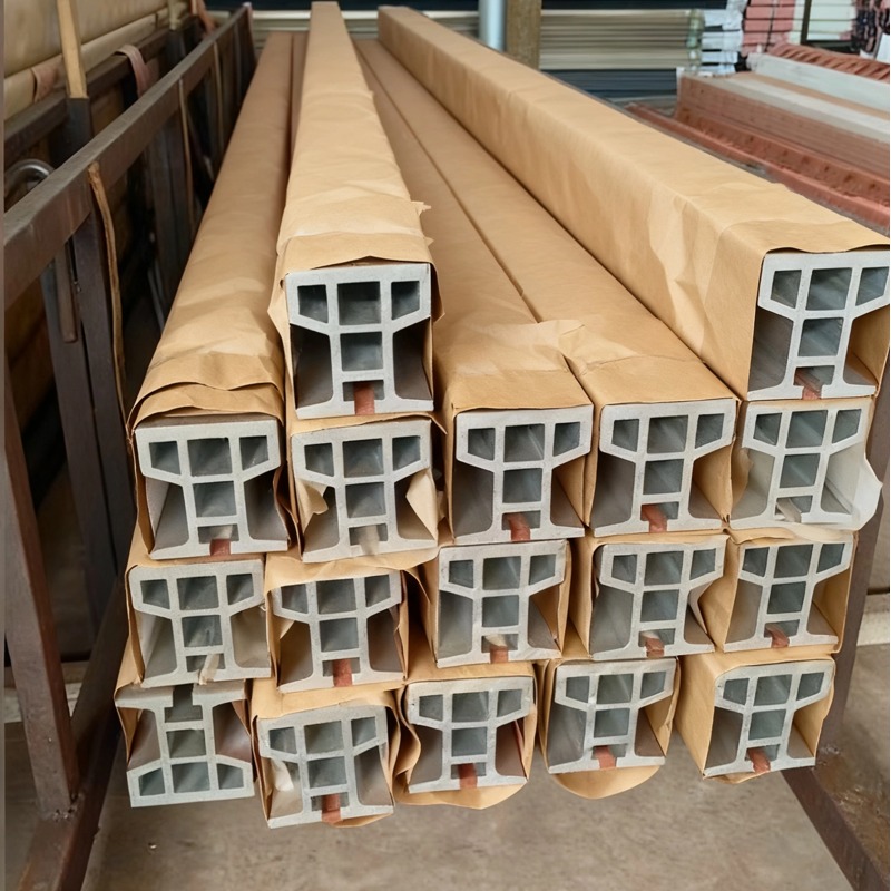
AGV-Navigationsschiene – ein Profil, drei Schnittstellen
Navigation sagt einem AGV, wo es ist; eine Schiene verhindert, dass es abdriftet. Warum SLAM-Linien weiterhin einen Schlitz nutzen und welche Schnittstellen nur in der Matrize erzeugt werden können.
Produktdetails
An AGV needs two things that are often confused with each other. It needs to know where it is, which is navigation, and it needs to stay on the line it is supposed to follow, which is guidance. Magnetic tape, QR codes, reflectors and SLAM all solve the first problem. None of them solves the second, and that is why a physical rail still exists on lines that already have perfect navigation.
The main navigation rail page deals with the magnetic tape slot and the tolerances it needs. This page is about the rail as an interface platform: how one section carries the hardware for three different navigation methods, and which of those decisions can be changed later.
Navigation is not guidance
A magnetic tape AGV reads a strip and corrects towards it. If the vehicle drifts 20 mm off the tape, it steers back. That correction is a continuous small oscillation, and on a light vehicle at speed it is the difference between a machine that tracks a line and a machine that wanders around it.
A rail removes the drift entirely. The guide rollers follow a machined groove, so lateral position is set mechanically rather than by a control loop. The navigation system then only has to answer "where along the rail am I", which is a far easier question and one that can be answered with a tape, a code or a reflector.
This is the case for keeping a physical track even on a modern SLAM-equipped vehicle: not because the vehicle cannot find its way, but because mechanical guidance gives repeatability at the dock that a control loop cannot match. A vehicle that must enter a charger or a conveyor interface within a millimetre benefits more from a groove than from a better algorithm.
Spezifikationen
| Element | Referenzwert | Hinweise |
|---|---|---|
| Legierung und Härtezustand | 6063-T5 | Light and dimensionally stable; adequate for light vehicles |
| Geradheit | Reference ≤ 1.0 mm over 10 m | Gemessen an der Lauffläche |
| Bearbeitungstoleranz | Reference ±0.02 to ±0.04 mm | Guide groove, tape slot, reflector seat |
| Tape slot widths | 10 mm, 15 mm, 30 mm | Fixed at die design; a section carries one width |
| Code marker seats | Milled pockets | Position set by machining, not by extrusion |
| Reflector groove | Extruded or machined | Height and angle matter more than depth |
| Oberfläche | Eloxiert | Low friction against the guide roller |
Reference values are from shipped sections. The value on your order is set by your drawing, and we confirm the achievable machined tolerance and slot dimensions in writing before you order.
One section, three navigation interfaces
The reason a single cross-section can serve magnetic, code and laser systems is that all three need the same three things: a defined position relative to the guide groove, a mounting feature, and protection from being stepped on or run over.
What differs is the tolerance that matters:
- Magnetic tape. The tape has to sit at a consistent height below the sensor and be held flat. The critical dimension is the slot depth and the flatness of its floor, not its width.
- QR or data matrix codes. The markers are read by a downward camera, so what matters is the pocket position along the rail and that the code face is not shadowed by the groove walls. Position tolerance of a few tenths is usually enough; optical clearance is what gets forgotten.
- Laser reflectors. These are mounted to the side of the rail on a vertical face, and what matters is the angular orientation of that face and its height above the floor. A reflector that leans by a degree loses range.
A well-designed section puts the guide groove on the centreline, the tape slot directly beneath the vehicle's sensor axis, and the reflector face on a vertical wall that is extruded flat rather than machined later. Getting all three into one die is a design exercise, and it is much cheaper than three separate sections.
The retrofit question: what you cannot add later
Navigation methods change. A line installed with magnetic tape five years ago may now want codes for better absolute positioning, or reflectors for a faster vehicle. The retrofit cost depends entirely on whether the section was designed with that possibility in mind.
Three features can only be created in the die, and none of them can be added afterwards without changing the section:
- A tape slot of a different width. If the slot is 15 mm, a 30 mm tape will not fit and a 10 mm tape will rattle. The slot width is fixed at extrusion.
- A second slot for a different method. A section with both a tape slot and a reflector face can be switched between methods; one with only a tape slot cannot.
- An enclosed cable or waveguide channel. If the vehicle's communication or power runs in the rail, that channel has to exist from the start.
What can be added later is machining: pockets for code markers, holes for brackets, and milled flats for reflectors. So the sensible design rule is to extrude every slot and channel the line might ever need, and to leave the machining until the navigation method is confirmed.
Slot tolerance, and why each method asks for something different
Aluminium extrusion holds a slot width to a few tenths as extruded. That is not enough for a tape slot, where the tape has to be held without being pinched, so the slot is machined after extrusion — typically to a tolerance of ±0.05 mm on width and ±0.1 mm on depth.
The depth tolerance is the one that matters most and the one most often missed. The sensor is calibrated for a tape face at a specific height. If the slot floor is 0.3 mm deeper than nominal along one part of the run, the sensor sees a weaker field and the vehicle treats it as a gap. The symptom is a vehicle that runs fine on one section of track and hesitates on another, which looks like a control fault and is a machining tolerance.
For code markers, the equivalent tolerance is positional: markers at an irregular pitch make the vehicle's absolute position estimate noisy, so the pitch should be set by a machined reference rather than by marking out on site.
Wo es nicht passt
Four cases where a navigation rail is the wrong investment. If the vehicle is a true SLAM unit that never repeats a path exactly, a fixed track removes the flexibility that the vehicle was bought for, and a simple taped route is cheaper. If the line is likely to be re-laid within a year, a bolted floor-level track that can be lifted and moved is better than one set into a levelling bed. If the environment has metal chips or abrasive dust, any open slot will fill and both the tape and the code markers will fail; a covered or side-mounted arrangement is needed. And if the navigation hardware vendor has not been chosen yet, the section should not be ordered, because the slot width and the reflector height are defined by that hardware and not by the rail.
Was für ein Angebot zu senden ist
- The navigation method, or the two methods you may switch between.
- The hardware drawings — tape width, sensor height above the tape, reflector height above the floor.
- The vehicle weight and guide roller arrangement, so the guide groove can be sized.
- Whether the layout includes curves, and whether the tape or codes have to follow them.
Send those and we can propose a section that carries all the interfaces you might need, while keeping the machining for the method you are actually installing.
FAQ
Welche Geradheit und Toleranz können Sie halten?
Reference 1.0 mm over 10 m straightness, with ±0.02 to ±0.04 mm on machined features and ±0.05 mm on a machined tape slot width. The tolerance that affects vehicle behaviour most is the slot depth consistency, so tell us the sensor height and we will quote against it. The value on your order is set by your drawing, and we confirm the achievable figures in writing before you order.
Can I switch from magnetic tape to QR codes later?
Partly. Code pockets can be machined into an existing rail, so if the section has enough flat surface above the guide groove, codes can be added. What cannot be changed is the tape slot width, so a 15 mm slot will still be a 15 mm slot.
Does the rail need to be anodised if it is indoors?
Yes, for the friction and wear reason rather than corrosion. The guide roller runs against the rail thousands of times a day, and bare aluminium against a polymer roller wears and generates dust. Anodising gives a harder surface and a lower friction coefficient.
Can the tape slot be covered to keep dust out?
Yes, with a brush strip or a thin cover that the sensor reads through. It is worth considering in any environment with chips or dust, because a filled slot causes exactly the symptom a failed sensor causes and is much harder to diagnose.
What pitch should the code markers be on?
Depends on the vehicle's camera field of view and speed — typically 300 to 1,000 mm. The important thing is uniformity: an irregular pitch makes the position estimate noisy even if every individual marker is correct.
Can one section serve both a magnetic AGV and a rail-guided RGV?
It can, if the guide groove is sized for the RGV's rollers and the tape slot is positioned for the AGV's sensor. The conflict is usually vertical space, because the RGV roller needs a deeper groove than the AGV needs. It is worth drawing both vehicles on the section before the die is cut.
Nächster Schritt
Send the navigation hardware drawings and the vehicle weight. We will come back with a section that carries the interfaces you need now, and the slots you are likely to need later, so the rail does not have to be replaced when the navigation method changes.
E-Mail: linjunbing@truetrustlv.com | Anrufen oder WhatsApp: +86 136 6644 0600
ANGEBOT ERHALTEN
Sobald Sie Ihre Anforderungen übermittelt haben, kontaktieren wir Sie so schnell wie möglich bezüglich Ihrer Produktanfrage.:AGV-Navigationsschiene – ein Profil, drei Schnittstellen