
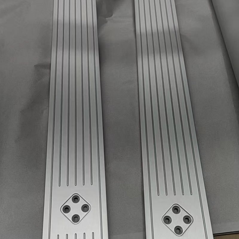
Aluminum Product Processing
CNC-Präzisionsschneiden von Aluminiumprofilen – Sägetoleranz
Wo ein gesägtes Ende schiefgeht: ±0,1 mm Länge ist leicht, Rechtwinkligkeit und Gehrungswinkel nicht. Wie ein Winkelfehler an der Verbindung zu einer sichtbaren Lücke wird.
Produktdetails
A cut looks like the simplest operation on a profile: a saw goes through, the piece comes off at the right length. In practice the cut face is the first surface in the tolerance chain, and every operation downstream inherits whatever it does wrong. A frame built from columns whose ends are 0.1 mm out of square does not close; the error does not average out, it accumulates at the joint.
We cut aluminium profiles on CNC double-head saws and high-speed circular saws with carbide blades, to a reference of ±0.1 mm on length, ≤ 0.1 mm perpendicularity on the end face, ±0.2° on angle, up to a 600 × 200 mm section and 6,020 mm standard stock length. Cut faces come off the saw at Ra ≤ 3.2 µm, clean enough to go straight to drilling and assembly.
This page is about where that accuracy comes from and where it stops being enough.
The cut is where the tolerance stack starts
Four numbers describe a sawn end, and each one fails differently:
| What is controlled | Referenzwert | What it becomes at assembly |
|---|---|---|
| Cut length | ±0.1 mm | Gap or interference at the joint; cumulative error over a run of stacked parts |
| Stirnflächenrechtwinkligkeit | ≤ 0.1 mm | Corner out of square; the frame leans and the diagonals differ |
| Mitre angle | ±0.2° | A visible gap on a mitre joint, magnified by the section width |
| Oberflächenrauheit | Ra ≤ 3.2 µm | Burrs that prevent faces seating; poor sealing on a gasketed joint |
Length is the number customers ask about, and it is the easiest of the four to hold. A CNC length stop with a first-piece check holds ±0.1 mm over a batch without difficulty. The other three are where the problems live.
Length is the easy tolerance; squareness is the one that costs money
Perpendicularity of 0.1 mm is a linear figure measured across the cut face. On a 100 mm deep section that is an angle of about 0.057°. Small. But a frame is a mechanism, not a single part:
- Four columns, each cut 0.1 mm out of square in the same direction, produce a top face that is out of level by 0.1 mm across the frame and a lean that is visible over a metre of height.
- Two columns cut out of square in opposite directions produce a 0.2 mm mismatch at the top rail, which is enough to stop a panel sitting flat.
- On a profile with two machined pads that must be coplanar after assembly, the cut error is added directly to the pad error, and the assembly tolerance has to absorb both.
This is why we measure squareness on the first piece with a dial gauge against a reference square rather than trusting the saw's angle setting, and why the blade and the feed are checked when a new section is loaded. A saw that is square on a 40 × 40 section is not automatically square on a 200 mm wide one, because the same 0.1 mm of blade tilt becomes a different angle over a different width.
The mitre problem: two angles add up
A 45° mitre joint is made of two cuts from two pieces. Each carries its own angular error, and at the joint the two errors combine. With a tolerance of ±0.2° per cut, the worst-case combination is 0.4° between the two faces.
Convert that into a gap, because that is what the customer sees. On a section 100 mm wide:
| Angular error at the joint | Gap on a 60 mm face | Gap on a 100 mm face | Gap on a 160 mm face |
|---|---|---|---|
| 0.1° | 0.10 mm | 0.17 mm | 0.28 mm |
| 0.2° | 0.21 mm | 0.35 mm | 0.56 mm |
| 0.4° (both cuts at limit) | 0.42 mm | 0.70 mm | 1.12 mm |
So on a wide decorative bezel, the angular tolerance — not the length tolerance — decides whether the corners look acceptable. Two practical consequences:
For a visible mitre, specify the gap, not the angle. "Splicing gap ≤ 0.1 mm on all four corners" is a requirement the supplier can work to and inspect. "Angle ±0.2°" leaves the customer doing trigonometry after delivery.
Cut both halves of a mitre on the same machine in the same setup where possible. The errors then track each other instead of opposing, and the joint closes. This is one reason we prefer to cut a frame's parts as a set rather than as separate orders.
What the blade is doing, and why aluminium is awkward for it
Aluminium cuts easily and that is the problem: soft, ductile chips weld to the tooth, and a built-up edge changes the effective geometry of the cutter. The result is a torn face, a burr on the exit side, and a blade that starts cutting oversize.
The controls are the blade and the parameters, not the operator's care:
- Tooth geometry. A triple-chip ground tooth is standard for aluminium: it slices the chip into three, which stops the soft material packing into the gullet.
- High surface speed, controlled feed per tooth. Aluminium wants speed. Too slow a feed per tooth rubs instead of cutting, which is exactly what produces the built-up edge.
- Lubrication. A mist or minimal-quantity system at the tooth. Dry cutting aluminium is possible, but the blade life and the face finish both fall away.
- Blade runout and flange condition. A blade with 0.05 mm of runout cuts a face that is 0.05 mm out of square no matter what the machine's angle scale says. This is checked on the machine, not assumed.
- Kerf. Each cut removes about 3–4 mm of material. On a part cut from a 6 m bar, that is real cost, and it is one of the reasons a design that needs six short pieces is priced differently from one that needs two long ones.
Thin walls and long sections: the two cuts that go wrong in the fixture
Thin walls. A saw is a pushing tool. On a section with 1.5 mm walls, the teeth can pull the wall into the kerf as the blade exits, and the last few millimetres of the cut close up behind the blade. The cut length comes out right and the end face comes out crushed. Dedicated fixtures that support the wall from inside, a finer tooth pitch and a reduced exit feed solve it, and it is a per-section solution, not a universal setting.
Long and heavy sections. A 6 m length of a heavy section is a beam that sags under its own weight. If it is supported at the ends only, the middle drops and the cut is made in a bent part; when the piece is laid flat afterwards, the ends no longer line up with where they were cut. Support stands at 1 to 1.5 m intervals, with the profile indicated level before the first cut, are the answer.
What we check on the first piece
Length against the drawing, end-face squareness with a dial gauge, angle on a mitre with a vernier protractor, and a visual check for burr on the exit edge. The first piece is kept as the reference for the batch. If a dimension is going to drift, it drifts from the first piece, and it is cheaper to find that on piece one than on piece two hundred.
Saw cut or milled face: where the boundary is
A saw cut is fast, cheap and, at Ra 3.2 µm with a clean blade, good enough for the great majority of frame and structural work. It is not a datum. Three cases need the face milled instead:
- The face is a datum for later machining. A saw cut carries a small crown and a slight angle from the blade path; machining a hole pattern from a sawn face transfers that error into the hole positions.
- The face has to seal. A gasket or an O-ring needs a flat, continuous surface. Sawn faces have a feed mark pattern that leaks, whatever the Ra says.
- The face is visible and has to match. On four exposed ends of a frame, the saw marks on one cut will not match the tool marks on another after anodising, and anodising makes the difference more obvious rather than less.
Where that line falls for a specific part is a decision we make with the drawing in front of us, and the end face milling page covers the machining side of it.
Spezifikationen
| Element | Referenzwert |
|---|---|
| Ausrüstung | CNC double-head saw, high-speed CNC circular saw, automatic precision saw |
| Cut length accuracy | ±0.1 mm |
| Stirnflächenrechtwinkligkeit | ≤ 0.1 mm |
| Angular accuracy | ±0.2° |
| Cut face roughness | Ra ≤ 3.2 µm, burr-free on the exit edge |
| Maximum section | 600 × 200 mm |
| Maximum stock length | 6,020 mm standard profile |
| Angles available | 90°, 45° mitre, any angle from 0 to 90°, contoured cuts |
| Legierungen | 6061-T6, 6063-T5, 6005-T6, 6082-T6, 7075-T5 |
| Kerf loss | Approximately 3–4 mm per cut |
| Cutting lead time | 24–48 hours for cutting only |
| Nachgelagert | Drilling, tapping, end-face milling, CNC machining, anodising in one order |
| Standard | GB/T 6892-2023 Hochpräzisionsgüte |
Wo es nicht passt
Sawing is the right first operation for most profile work. It is the wrong answer in these cases, and we would rather say so at quotation than at delivery:
- Tolerances below ±0.05 mm on length. That is beyond what a saw holds repeatably in production. The part needs to be cut oversize and machined to length.
- Faces that must be flat to better than about 0.05 mm. A saw cut is not flat at that level; it has a slight crown from the blade path.
- Sections too large for the saw envelope. Above 600 × 200 mm, the part is cut on a different machine or machined from a larger blank, and the cost changes accordingly.
- Very small quantities of a part that also needs machining. If the part is going on a machining centre anyway, cutting it there as part of the first operation usually beats a separate sawing step plus a second setup.
- Parts where the cut face is a cosmetic feature. A milled and anodised face is a design statement; a sawn face is a manufacturing step. If the end will be seen, decide that early.
FAQ
What accuracy can you hold on a cut length?
Reference ±0.1 mm on length, ≤ 0.1 mm end-face perpendicularity and ±0.2° on angle, with Ra ≤ 3.2 µm on the cut face. Those are capability references: the value on your order is set by your drawing, and the achievable figure depends on the section size, the wall thickness and whether the part needs special support. We confirm the achievable tolerance in writing before the batch starts.
Is a saw cut good enough to assemble directly?
For most frames, yes. A clean cut at Ra 3.2 µm with square ends goes straight to drilling and assembly without deburring. It stops being enough when the face is a datum for later machining, has to seal against a gasket, or is visible on the finished product.
Why does my mitre joint show a gap when each cut is within tolerance?
Because the two angular errors add at the joint. Two cuts each at the ±0.2° limit can meet at 0.4°, which on a 100 mm face is a 0.7 mm gap. The fix is to specify the gap rather than the angle, and to have both halves of the joint cut on the same machine as a set.
Can you cut profiles with a wall thickness under 1.5 mm?
Yes, with a fixture that supports the wall from inside and a reduced exit feed. Without that support the wall collapses into the kerf as the blade leaves, and the length is right while the face is crushed. Send the section drawing and we will say whether a fixture is needed.
What is the longest piece you can cut?
6,020 mm from standard stock. Longer parts are possible from mill-length material, but the handling and the support become the constraint rather than the saw, so it is quoted per part.
Does cutting damage the anodised finish?
The cut removes the coating and leaves bare aluminium on the face, so cutting has to happen before anodising. If a part must be cut after coating for a site reason, expect a visible bare edge and plan a touch-up.
Can you cut, drill and anodise in one order?
Yes. Cutting, drilling and tapping, end-face milling, CNC machining and surface treatment are handled as one route, so the part arrives finished rather than moving between suppliers. That matters most on frames, where the cut and the holes have to agree with each other.
Senden Sie Ihre Zeichnung
Email the section drawing with the cut list, the angles and the tolerance that matters on each end to linjunbing@truetrustlv.com, or send it on WhatsApp at +86 136 6644 0600. You will get a cut plan, a note on which ends need milling rather than sawing, and a written tolerance statement for the batch.
ANGEBOT ERHALTEN
Sobald Sie Ihre Anforderungen übermittelt haben, kontaktieren wir Sie so schnell wie möglich bezüglich Ihrer Produktanfrage.:CNC-Präzisionsschneiden von Aluminiumprofilen – Sägetoleranz